
UPR Chrome Moly K-Member Kit Install with coil overs
Weight:
UPR K-Member with A-Arms = 29lbs
Eibach 250 lb springs = 8lbs
STOCK PARTS:
Subframe/oil pan protector = 16lbs
A-Arms (2) = 28.75 lbs
K-Member = 51.75
Springs (2) = 19.25 lbs
NET WEIGHT LOSS: 79 pounds! I’ve seen different numbers floating around. I have a quality doctors’ scale and carefully weighed the items twice.
DIFFICULTY: If you have to ask, don’t do it. You need to have a good set of tools. 1 person can do the whole job with no assistance.
PICTURES FOLLOW THE WRITE UP
TIPS:
BE SAFE! Raise the car onto 4 or 6 jack stands making sure everything is correctly placed and stable. Use something strong on either side of the car frame that will keep the car from landing on you if it were to fall. I use my front rims and tires with some boards on top just for this reason.
I used a heavy duty puller tool to “pop” the control arm and the A-Arm loose from the spindle. This worked quite well and it was surprising how much pressure it took to pop them off.
Use a jack and some wood beneath the trans and put just a bit of upward pressure before removing the K-Member. This will support the engine while the swap-out takes place.
The steering column connector to the steering rack is a 13mm bolt that pinches a brass connector to the spindle on the steering rack. Remove this bolt, then get a fairly large standard screw driver and insert it into the locking gap in the brass connector. Tap it with a mallet to spread the brass connector open a bit. This will make it much easier to disconnect from the steering rack. NOTE: the shaft is made to retract several inches, so you can gently tap on the brass connector to get it to release and the shaft behind it will retract allowing it to back off the spindle on the steering rack.
A ground wire and screw on the drivers’ side will be directly beneath part of the new frame. Remove the screw to get it out of the way. There happens to be the guide bracket for the clutch cable just 2 inches away. You can relocate the ground wire here or chose your own location.
On the passenger side there are 3 metal brake lines that need to be bent a bit to get them out of the way of the k-member where it bolts to the frame inside the fender well area. Not a big deal to bend them with a screwdriver or similar tool to get them out of the way. They only need to move about ½” and it won’t look as pretty as it did before, so deal with it!
Either attach the A-Arms to the K-Member prior to bolting it in place OR make sure you attach them before you reinstall the steering rack. You cannot get the front large bolt in the A-Arm while the steering rack is in place. Also, one of the K-Member’s rear support bolts will have to be removed to get the other large bolt inserted properly.
I was able to install the standard oil filter (not the shorty) because I made sure to tap the K-Member to the rear of the car just enough for my filter to clear properly. It’s really close! 1/16” can make the difference.
When you remove the calipers and free the spindle, hang them up in the fender well out of the way. They need to be out of your way and you don’t want them hanging by the brake lines anyway. Tie wraps work well here.
If you want to have a quiet suspension, lightly grease all rubber/urethane to metal connections. Some people will not agree with this, but this was my preference and it is very quiet!
GET TO WORK:
Remove wheels, calipers, rotors, strut bolts, springs and control rods. Secure spindles and calipers. I place a jack beneath the a-arm before I popped it loose from the spindle. I didn’t want a 10lb spring flying out at me. Once the a-arm was released from the spindle I slowly let the jack lower until the spring had no tension.
Remove subframe/oil pan protector. This is just a bunch of bolts, nothing special.
Remove stock A-Arms, keep large bolts and nuts for reassembly. Notice the large bolts point to the center of the a-arm with nuts in the middle.
Remove steering rack and column connector. The long bolts and rubber bushings are reused on the steering rack. Two lines are attached to the rack. Don’t remove anything, but take care not to damage them.
Loosen the bolts securing stock K-Member.
Use a jack to support engine now. With the bolts already loosened, it’s easy to see when you’ve got the engine supported properly.
Remove K-Member by removing all 8 bolts. You will be reusing these bolts.
Should you require any other work, this is the time to do it! My pan gasket needed to be replaced. This is also a great time to inspect for any fluid leaks, hoses, clamps, etc. Also a great opportunity to do some cleaning.
Insert tubular k-member and check that it will fit. You need to have moved the ground wire from the drivers’ side already. Don’t worry yet about the brake lines on the passenger side. I had no fitment issues what-so-ever. Now just start 2 bolts on each side, one in the wheel well and one on the rear support. This will hold the new k member in place for the next step.
Now is the time to get the brake lines repositioned around the end of the k-member support. Just use your brains here and bend them just enough to get the support under the three lines. As soon as the support is under them put the other bolt in the support but don’t tighten it down yet. Start the rest of the bolts without snugging them down.
Now, you want to use the mounting holes in your car frame as a guide to center and straighten the k member as well as possible. Since there is play in each of the k member’s slots there is “wiggle room” for minor adjustments. I used a rubber mallet to tap the k member into position and then began to tighten the bolts.
The rear support bolts, 4 of them, are torqued to 54ft lbs, if you want them torque per original Ford specs. The side frame bolts are 89 ft lbs, and the engine mount bolts are at 111 ft. lbs.
CHECK YOUR WORK NOW TO MAKE SURE YOU HAVE THINGS IN ORDER.
Make sure the a-arms are connected. They should be tightened just enough to allow the a arm to drop down by itself if not supported.
Now, my choice here was to reinstall the steering rack. I got the two main mounts started first, then reattached the steering column. Remember, the column retracts and makes this easy if you had spread the brass connector in the earlier removal step. Clean up the connector parts and put a tad of grease and it should slip right on. Make sure it is on all the way and then tighten it. THIS IS IMPORTANT. SHOULD THIS CONNECTION COME APART YOU WILL NOT BE GUIDING YOUR CAR WITH THE STEERING WHEEL!
Finish tightening up the two mounts for the steering rack, again taking care that these are tightened correctly.
Now is a good time to remove the existing strut mounts from under the hood and mount your caster/camber plates. These will have their own instructions. One thing is for sure, you don’t want the strut dangling in your way when you replace the spindle and control arm.
The k-member came with two thick washers and 4 large normal thickness washers. The two thick ones are used on the new ball joint threaded stud. Insert a arm stud into spindle, put the thick washer on the stud, and then start the new cotter pin styled bolt on that. Don’t tighten it. Screw the nut down to where the cotter pin hole shows through the nut on the a arm ball joint and see if it is loose or tight at that point. It needs to be tight! Use the additional washers under the nut if necessary so that the nut is tight before you put the cotter pin in. Mine needed three extra washers on each side to be nice and tight. Screw in the zert fitting provided for these joints underneath and tighten accordingly. This is a good time to grease them because you still have lots of room to workl. Use axle grease.
Now connect the control arm to the front side of the spindle and start the old cotter pin styled nut on that. Go ahead and tighten it down. NOTE: I LIFTED THE RUBBER BOOTS ON THE CONTROL ARMS AND CLEAND ALL THE OLD GREASE AND GRIT FROM THEM. If you do this then use the zert and pump them up with fresh axle grease.
Assuming you’ve followed directions on setting up you CC’s and your coil overs, it’s time to mount the struts. Make sure you have the spacers you want placed on the strut before inserting it into the strut tower. Start a nut on top of the CCs to keep the strut in place. Now, lift the spindle assembly up and line up the mounting holes with the strut and get a bolt in. This will hold it now and make it easy to insert the second bolt. These are also the original mounting bolts you removed earlier. There is also a brake line mount that attaches to these bolts. Make sure everything is tight, cotter pins are in properly and ball joints greased.
Now you can reinstall the calipers and rotors.
NOTE: Now is also a great time to pop the cap off the end of the spindle and pack grease into the wheel bearing. Gently pound cap back into spindle when you’re finished.
Now, adjust your coil over spring adjustment even on each side. My guess is they should be in the top half of the adjustment range or the car will sit too low. You wont know until you sit the car back down and you’ll probably adjust once or twice more.
Likely, you tires will be toed outward and you can loosen the locknut on the control arms and bring them in by eye. The lower the car is, the more the camber will be off.
If you’ve completed the CC assembly up top and have the height where you want it (measure from the ground to the fender well in the center of the tire on each side to make sure the car sits even side to side) then it’s time to go get an alignment done!
CONGRATULATIONS! You may or may not be done now. If the alignment cannot bring the adjustments within tolerances, you will need to lift the car again, loosen the 8 bolts mounting the k member, and tap it this way or that according to the alignment issues. With the play in the k member it is possible it cannot be brought into proper alignment without a final adjustment of the position of the k member. If this happens you'll have to go back to finish the computer alignment.
Mine required a readjustment of the k-member to get caster and camber within tolerances. This is a better option than starting to elongate adjustment slots on your CCs.
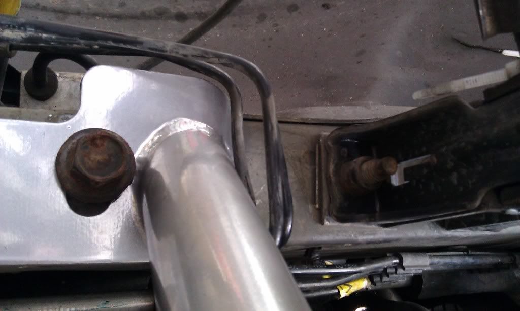
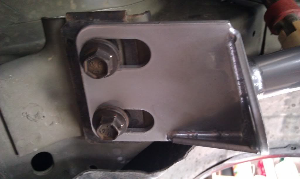
FINALLY, check out the pictures of the rear mounting points for the k-member. You’ll see one with just the bolts and you’ll see one with a plate I fabricated to transfer stress to the entire mounting surface and reinforce the k-member itself.

Relocated groundwire

Stock a-arm ball joint. Use the puller on this puppy

Stock sub frame/pan protector. Gotta say bye bye to this.
Brake line relocation completed
Steering column connection
Unreinforced rear k member support
Reinforced support

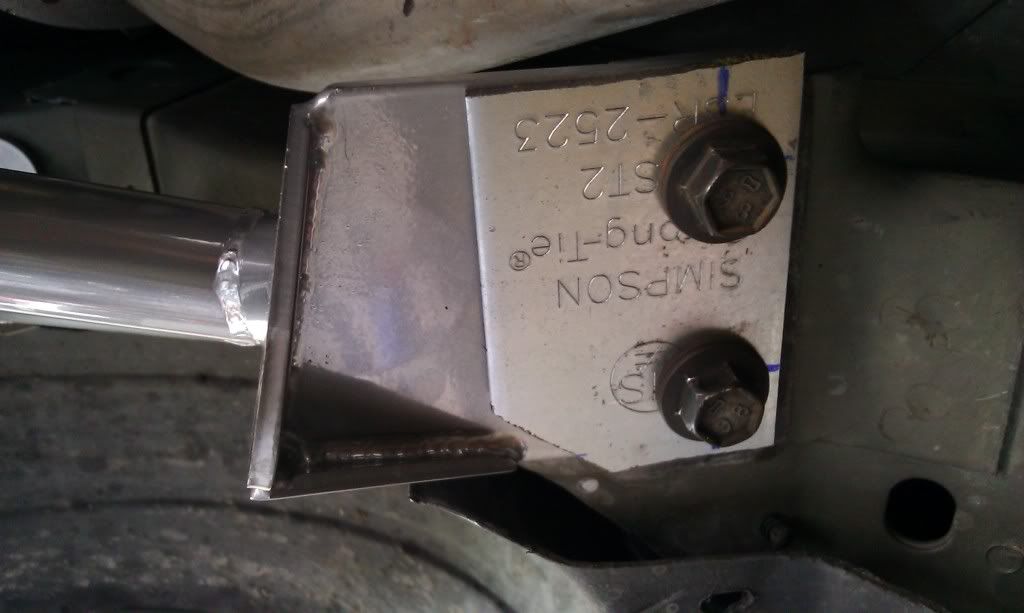
Simpson strong tie used to fabricate supports
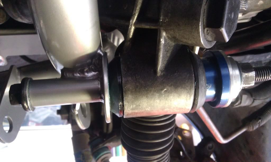
one of the 2 steering rack mounts on new k member
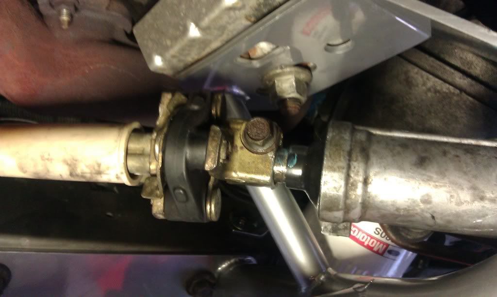
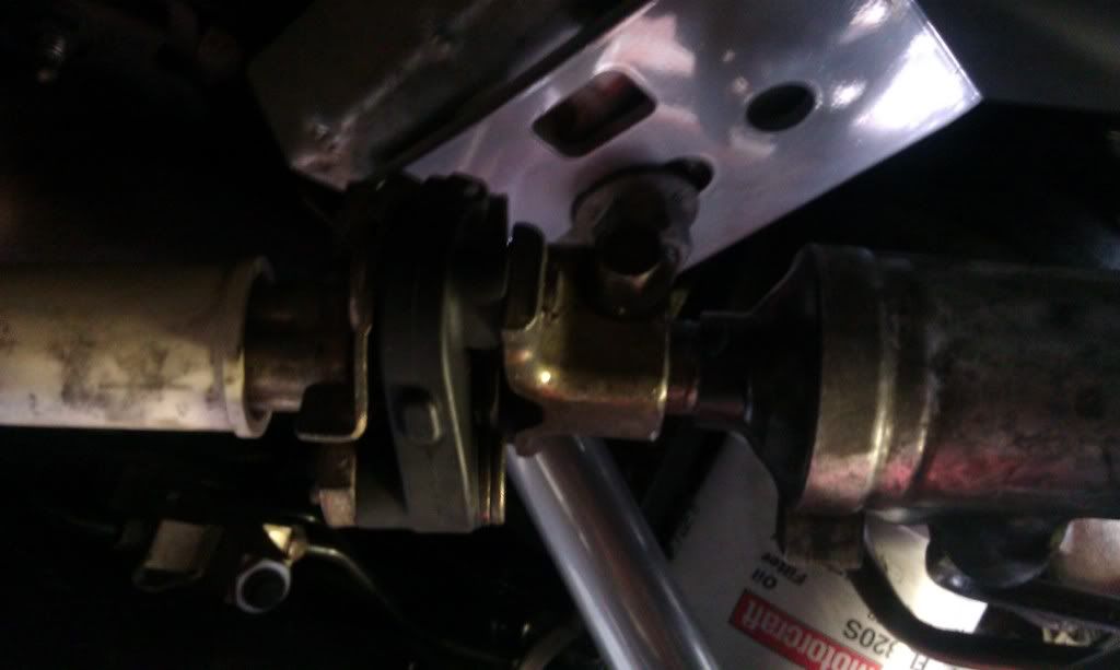
Steering column after reinstall of steering rack
It helps to take a few shots before disassembly. Make great reference items if you're not certain about something.
Weight:
UPR K-Member with A-Arms = 29lbs
Eibach 250 lb springs = 8lbs
STOCK PARTS:
Subframe/oil pan protector = 16lbs
A-Arms (2) = 28.75 lbs
K-Member = 51.75
Springs (2) = 19.25 lbs
NET WEIGHT LOSS: 79 pounds! I’ve seen different numbers floating around. I have a quality doctors’ scale and carefully weighed the items twice.
DIFFICULTY: If you have to ask, don’t do it. You need to have a good set of tools. 1 person can do the whole job with no assistance.
PICTURES FOLLOW THE WRITE UP
TIPS:
BE SAFE! Raise the car onto 4 or 6 jack stands making sure everything is correctly placed and stable. Use something strong on either side of the car frame that will keep the car from landing on you if it were to fall. I use my front rims and tires with some boards on top just for this reason.
I used a heavy duty puller tool to “pop” the control arm and the A-Arm loose from the spindle. This worked quite well and it was surprising how much pressure it took to pop them off.
Use a jack and some wood beneath the trans and put just a bit of upward pressure before removing the K-Member. This will support the engine while the swap-out takes place.
The steering column connector to the steering rack is a 13mm bolt that pinches a brass connector to the spindle on the steering rack. Remove this bolt, then get a fairly large standard screw driver and insert it into the locking gap in the brass connector. Tap it with a mallet to spread the brass connector open a bit. This will make it much easier to disconnect from the steering rack. NOTE: the shaft is made to retract several inches, so you can gently tap on the brass connector to get it to release and the shaft behind it will retract allowing it to back off the spindle on the steering rack.
A ground wire and screw on the drivers’ side will be directly beneath part of the new frame. Remove the screw to get it out of the way. There happens to be the guide bracket for the clutch cable just 2 inches away. You can relocate the ground wire here or chose your own location.
On the passenger side there are 3 metal brake lines that need to be bent a bit to get them out of the way of the k-member where it bolts to the frame inside the fender well area. Not a big deal to bend them with a screwdriver or similar tool to get them out of the way. They only need to move about ½” and it won’t look as pretty as it did before, so deal with it!
Either attach the A-Arms to the K-Member prior to bolting it in place OR make sure you attach them before you reinstall the steering rack. You cannot get the front large bolt in the A-Arm while the steering rack is in place. Also, one of the K-Member’s rear support bolts will have to be removed to get the other large bolt inserted properly.
I was able to install the standard oil filter (not the shorty) because I made sure to tap the K-Member to the rear of the car just enough for my filter to clear properly. It’s really close! 1/16” can make the difference.
When you remove the calipers and free the spindle, hang them up in the fender well out of the way. They need to be out of your way and you don’t want them hanging by the brake lines anyway. Tie wraps work well here.
If you want to have a quiet suspension, lightly grease all rubber/urethane to metal connections. Some people will not agree with this, but this was my preference and it is very quiet!
GET TO WORK:
Remove wheels, calipers, rotors, strut bolts, springs and control rods. Secure spindles and calipers. I place a jack beneath the a-arm before I popped it loose from the spindle. I didn’t want a 10lb spring flying out at me. Once the a-arm was released from the spindle I slowly let the jack lower until the spring had no tension.
Remove subframe/oil pan protector. This is just a bunch of bolts, nothing special.
Remove stock A-Arms, keep large bolts and nuts for reassembly. Notice the large bolts point to the center of the a-arm with nuts in the middle.
Remove steering rack and column connector. The long bolts and rubber bushings are reused on the steering rack. Two lines are attached to the rack. Don’t remove anything, but take care not to damage them.
Loosen the bolts securing stock K-Member.
Use a jack to support engine now. With the bolts already loosened, it’s easy to see when you’ve got the engine supported properly.
Remove K-Member by removing all 8 bolts. You will be reusing these bolts.
Should you require any other work, this is the time to do it! My pan gasket needed to be replaced. This is also a great time to inspect for any fluid leaks, hoses, clamps, etc. Also a great opportunity to do some cleaning.
Insert tubular k-member and check that it will fit. You need to have moved the ground wire from the drivers’ side already. Don’t worry yet about the brake lines on the passenger side. I had no fitment issues what-so-ever. Now just start 2 bolts on each side, one in the wheel well and one on the rear support. This will hold the new k member in place for the next step.
Now is the time to get the brake lines repositioned around the end of the k-member support. Just use your brains here and bend them just enough to get the support under the three lines. As soon as the support is under them put the other bolt in the support but don’t tighten it down yet. Start the rest of the bolts without snugging them down.
Now, you want to use the mounting holes in your car frame as a guide to center and straighten the k member as well as possible. Since there is play in each of the k member’s slots there is “wiggle room” for minor adjustments. I used a rubber mallet to tap the k member into position and then began to tighten the bolts.
The rear support bolts, 4 of them, are torqued to 54ft lbs, if you want them torque per original Ford specs. The side frame bolts are 89 ft lbs, and the engine mount bolts are at 111 ft. lbs.
CHECK YOUR WORK NOW TO MAKE SURE YOU HAVE THINGS IN ORDER.
Make sure the a-arms are connected. They should be tightened just enough to allow the a arm to drop down by itself if not supported.
Now, my choice here was to reinstall the steering rack. I got the two main mounts started first, then reattached the steering column. Remember, the column retracts and makes this easy if you had spread the brass connector in the earlier removal step. Clean up the connector parts and put a tad of grease and it should slip right on. Make sure it is on all the way and then tighten it. THIS IS IMPORTANT. SHOULD THIS CONNECTION COME APART YOU WILL NOT BE GUIDING YOUR CAR WITH THE STEERING WHEEL!
Finish tightening up the two mounts for the steering rack, again taking care that these are tightened correctly.
Now is a good time to remove the existing strut mounts from under the hood and mount your caster/camber plates. These will have their own instructions. One thing is for sure, you don’t want the strut dangling in your way when you replace the spindle and control arm.
The k-member came with two thick washers and 4 large normal thickness washers. The two thick ones are used on the new ball joint threaded stud. Insert a arm stud into spindle, put the thick washer on the stud, and then start the new cotter pin styled bolt on that. Don’t tighten it. Screw the nut down to where the cotter pin hole shows through the nut on the a arm ball joint and see if it is loose or tight at that point. It needs to be tight! Use the additional washers under the nut if necessary so that the nut is tight before you put the cotter pin in. Mine needed three extra washers on each side to be nice and tight. Screw in the zert fitting provided for these joints underneath and tighten accordingly. This is a good time to grease them because you still have lots of room to workl. Use axle grease.
Now connect the control arm to the front side of the spindle and start the old cotter pin styled nut on that. Go ahead and tighten it down. NOTE: I LIFTED THE RUBBER BOOTS ON THE CONTROL ARMS AND CLEAND ALL THE OLD GREASE AND GRIT FROM THEM. If you do this then use the zert and pump them up with fresh axle grease.
Assuming you’ve followed directions on setting up you CC’s and your coil overs, it’s time to mount the struts. Make sure you have the spacers you want placed on the strut before inserting it into the strut tower. Start a nut on top of the CCs to keep the strut in place. Now, lift the spindle assembly up and line up the mounting holes with the strut and get a bolt in. This will hold it now and make it easy to insert the second bolt. These are also the original mounting bolts you removed earlier. There is also a brake line mount that attaches to these bolts. Make sure everything is tight, cotter pins are in properly and ball joints greased.
Now you can reinstall the calipers and rotors.
NOTE: Now is also a great time to pop the cap off the end of the spindle and pack grease into the wheel bearing. Gently pound cap back into spindle when you’re finished.
Now, adjust your coil over spring adjustment even on each side. My guess is they should be in the top half of the adjustment range or the car will sit too low. You wont know until you sit the car back down and you’ll probably adjust once or twice more.
Likely, you tires will be toed outward and you can loosen the locknut on the control arms and bring them in by eye. The lower the car is, the more the camber will be off.
If you’ve completed the CC assembly up top and have the height where you want it (measure from the ground to the fender well in the center of the tire on each side to make sure the car sits even side to side) then it’s time to go get an alignment done!
CONGRATULATIONS! You may or may not be done now. If the alignment cannot bring the adjustments within tolerances, you will need to lift the car again, loosen the 8 bolts mounting the k member, and tap it this way or that according to the alignment issues. With the play in the k member it is possible it cannot be brought into proper alignment without a final adjustment of the position of the k member. If this happens you'll have to go back to finish the computer alignment.
Mine required a readjustment of the k-member to get caster and camber within tolerances. This is a better option than starting to elongate adjustment slots on your CCs.
FINALLY, check out the pictures of the rear mounting points for the k-member. You’ll see one with just the bolts and you’ll see one with a plate I fabricated to transfer stress to the entire mounting surface and reinforce the k-member itself.
Relocated groundwire
Stock a-arm ball joint. Use the puller on this puppy
Stock sub frame/pan protector. Gotta say bye bye to this.
Brake line relocation completed
Steering column connection
Unreinforced rear k member support
Reinforced support
Simpson strong tie used to fabricate supports
one of the 2 steering rack mounts on new k member
Steering column after reinstall of steering rack
It helps to take a few shots before disassembly. Make great reference items if you're not certain about something.
Last edited: